Vfd Panel Wiring Diagram
Danfoss vfd with bypass wiring diagram. It shows the elements of the circuit as simplified shapes, as well as the power as well as signal connections between the devices.
wiring diagram for vfd Wiring Diagram and Schematic
The second enclosure is bigger and houses all the relays and other accessories that are in the wiring diagrams.
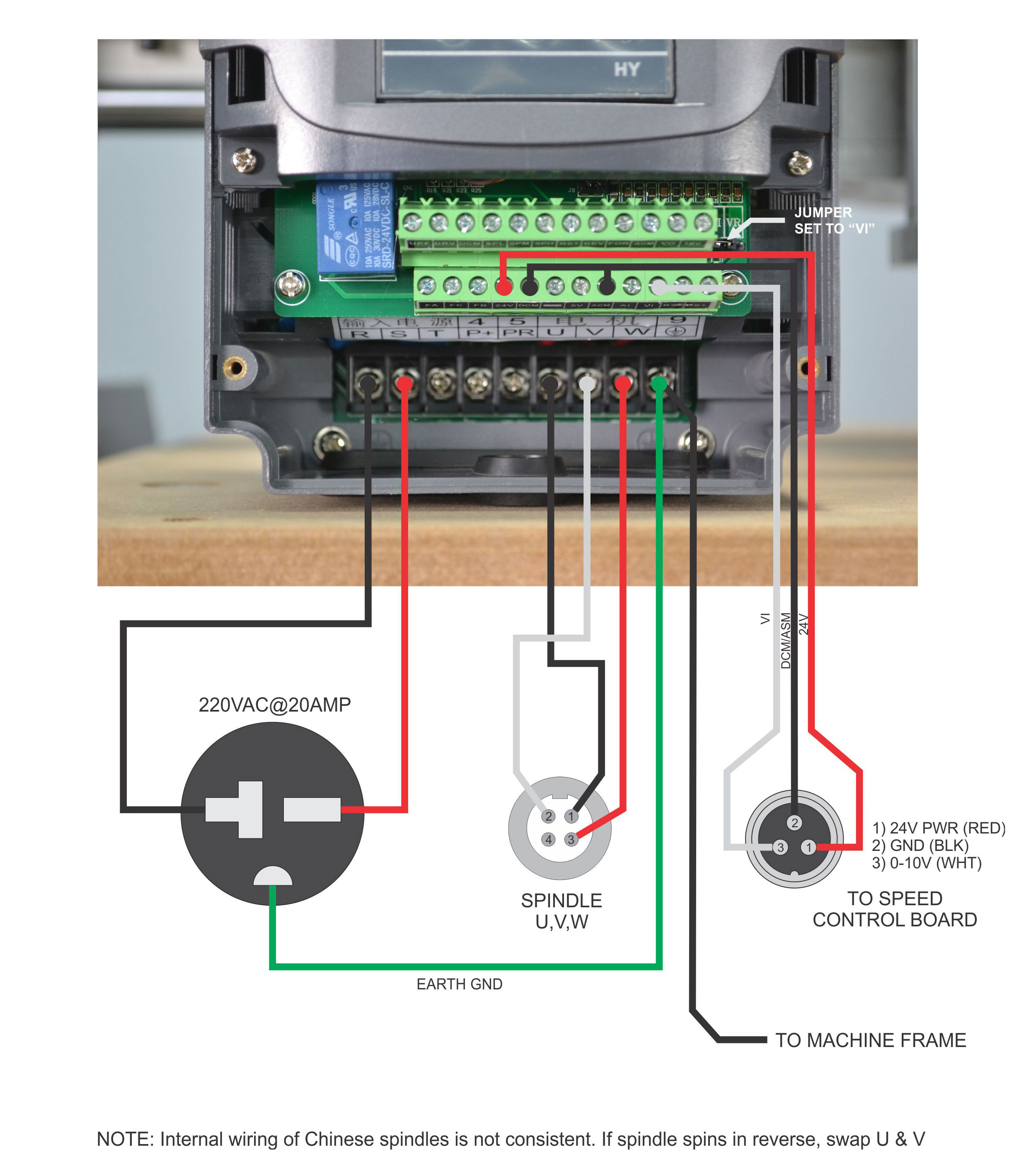
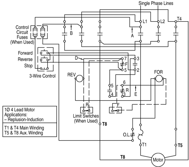
Vfd panel wiring diagram. (1) the vfd's three phase ac input terminals (r/l1, s/l2, t/l3) the power line's input terminals connect to 3 phase ac power through line protection or leakage protection breaker, it does not need to consider the connection of phase sequence. A wiring diagram usually provides details about the loved one position… It shows the parts of the circuit as simplified shapes, as well as the power as well as signal connections in between the tools.
Vfd start stop wiring diagram. This literature applies to units produced after 11396 software version 20 or greater diagram index unit label diagram unit voltage label diagram type serial number effective label diagram figure no. Connect or do wiring as per vfd side drawing, you take +24 v from the vfd pcb directly.
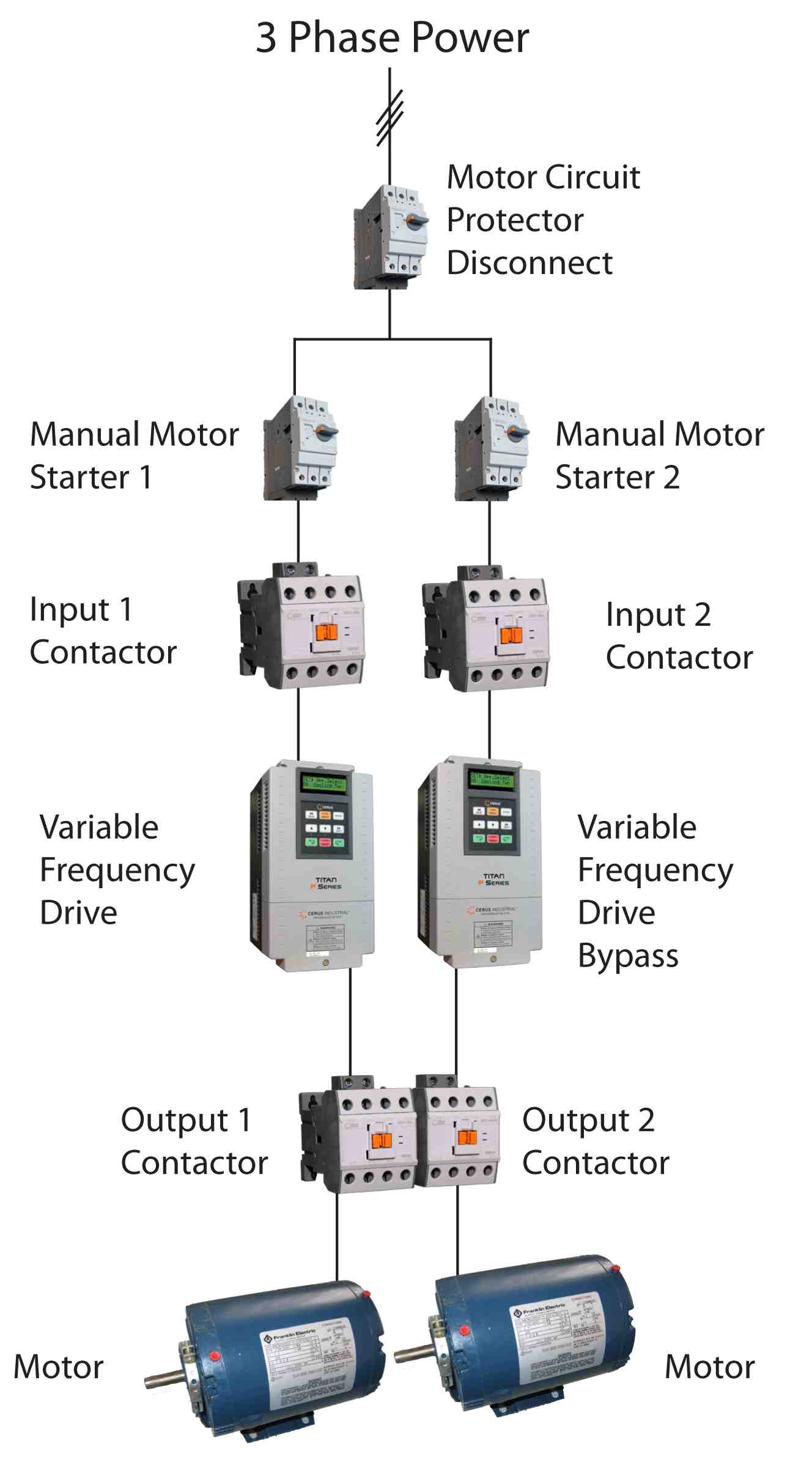
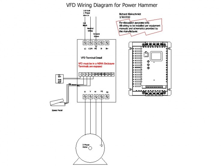
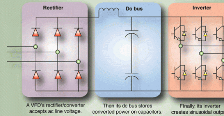
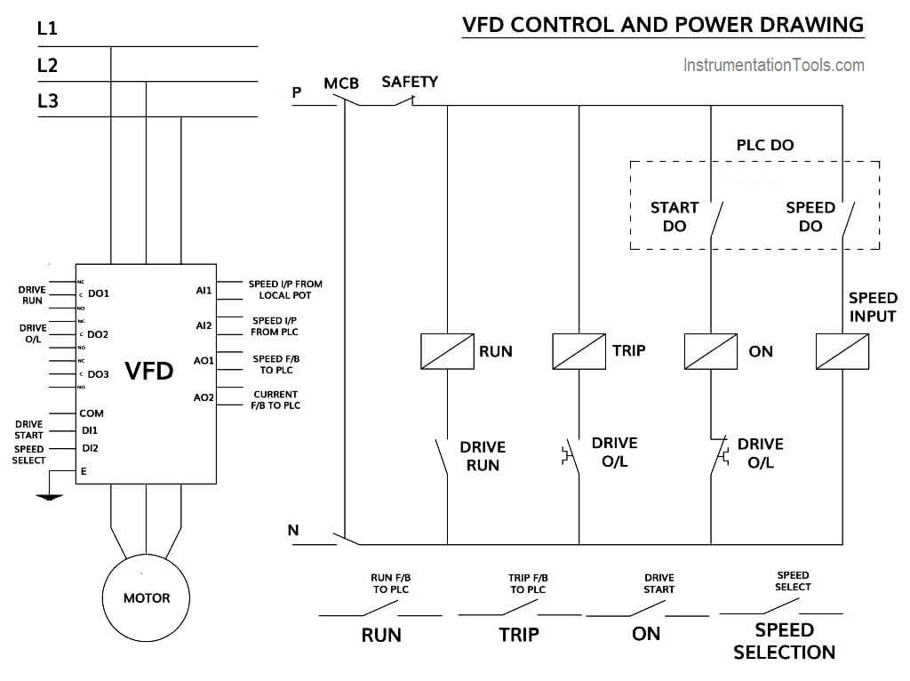
Control and power wiring diagrams. The vfd main circuit terminals shown as below figure. In bypass the motor is operated directly from line input power.
343 wire size 19 344 wire type rating. Layout monster vfd wiring diagrams diagram showing power in instructions add ons plc hmi and motor circuit 3 phase induction using variable sd control frequency drive for constant skills hands output board spindle start stop. After applying the dc bus voltage across the igbts without the motor connected adjust the pwm 1k preset until the voltage across the rails become equal to the intended motor voltage specs.
8 16 2020 vfd control wiring diagram wiring diagram is a simplified all right pictorial representation of an electrical circuit it shows the components of the circuit as simplified shapes and the capacity and signal connections with the devices. Ground the vfd el using the ground terminal. Push to make / ptm switch use to start the motor and push to brake / ptb switch use to stop the motor.
A wiring diagram generally offers info about… It contains guidelines and diagrams for different varieties of wiring strategies and other items like lights, home windows, and so forth. Vfd panel wiring diagram sample.
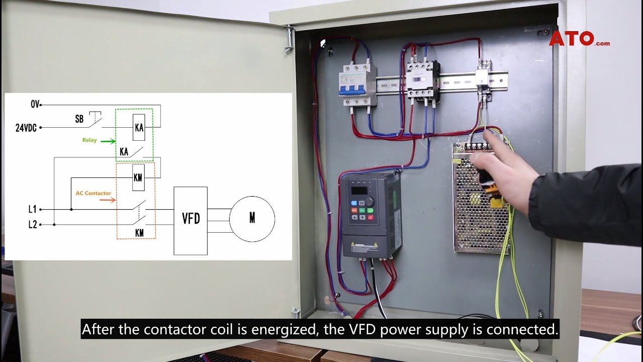
K1 no1, pb3, pb4, pb5 should be of potential free contact. Application note ap0400076en vfd wiring best practices effective july 2014 2 eaton corporation www.eaton.com control wiring similar consideration need to be taken when looking at the control wiring. A wiring diagram is a streamlined conventional photographic depiction of an electrical circuit.
Ts1, enclosure fan1 standard on all nema 3r panels. Monitoring danfoss vfd in bypass october 04. Posted on may 14, 2018 august 9, 2018 by headcontrolsystem.
Variety of vfd panel wiring diagram. Enclosure fan2 on 25hp and larger at 480v. It shows what sort of electrical wires are interconnected and can also show where fixtures and components could possibly be attached to the system.
Frame 5, 2 contactor wiring diagram m34225 all panels shipped with vfd default programming parameters. A wiring diagram is a simplified conventional pictorial representation of an electric circuit. The vfds showed in the video are the d720s (230v single phase) and the d720 (230v three phase).
3 contactor wiring diagram m34045 dis1 main fused disc. Then as per vfd logic if dl 1(digital logic) goes high vfd start to feed the output voltage, motor start rotating. Check connections of l1, l2, l3;
I am putting together my first cnc, but need help with the wiring for the control box for the vfd to make sure it will work and i don't blow my self up. Abb vfd control circuit diagram furthermore pump panels moreover abb dc motor wiring diagram also loncin 50cc 4 wheeler wiring diagram as well as single phase ac motor control furthermore vfd schematic diagram pdf as well as 1a0p along with d3v furthermore vfd control wiring diagram in addition air pressor industry along with electrical drives ac drives vfd. Vfd start stop wiring diagram:
If customer safety interlock is used, remove j1. Vfd control panel diagram and vfd full of zip principle youtube. Vfd start stop wiring diagram:
Main power comes first to that enclosure. Assortment of vfd panel wiring diagram. It reveals the parts of the circuit as simplified shapes, and the power and signal connections in between the tools.
Danfoss vfd wiring diagram wiring diagram data schema pioneer avic n1 wiring diagram. A wiring diagram is a straightforward visual representation in the physical connections and physical layout of the electrical system or circuit. The control circuit is separate from the motor circuit.
A vfd drive controls the motor speed. 1 the vfd s three phase ac input terminals r l1 s l2 t l3 the power line s input terminals connect to 3 phase ac power through line protection or leakage protection breaker it does not need to consider the connection of phase sequence. See table 12 for their functions.
Set dip switches as needed. Vfd wiring diagram how do. When you press the on push k1 contactor will hold and k1 no1 become nc.
One is dedicated to the vfd with its electrical disconnect and a fuse. Vfd panel wiring diagram pdf. It is worth mentioning, that i used two enclosures.
Start stop station wiring diagram. Please feel free to comment or ask questions should you have any.
Beginner VFD Wiring


VFD control wiring diagram । Engineers CommonRoom YouTube
VFD Wiring Diagram SD Metalworks

Vfd Panel Wiring Diagram

Vfd Panel Wiring Diagram

wiring diagram for vfd Wiring Diagram and Schematic
42 CONTROL CIRCUIT DIAGRAM OF VFD, DIAGRAM VFD OF CONTROL CIRCUIT Circuit

Vfd Starter Panel Wiring Diagram Diagram Vfd Starter Panel Wiring Diagram Full Version Hd
Vfd Panel Wiring Diagram Gallery Wiring Diagram Sample
Vfd Lathe Wiring Diagram


Vfd Starter Panel Wiring Diagram Diagram Vfd Starter Panel Wiring Diagram Full Version Hd
Vfd Panel Wiring Diagram Gallery Wiring Diagram Sample

Request for pictures of VFD installations on lathes
Vfd Starter Panel Wiring Diagram Diagram Vfd Starter Panel Wiring Diagram Full Version Hd

VFD Panel Paneling, Block diagram, Inductors
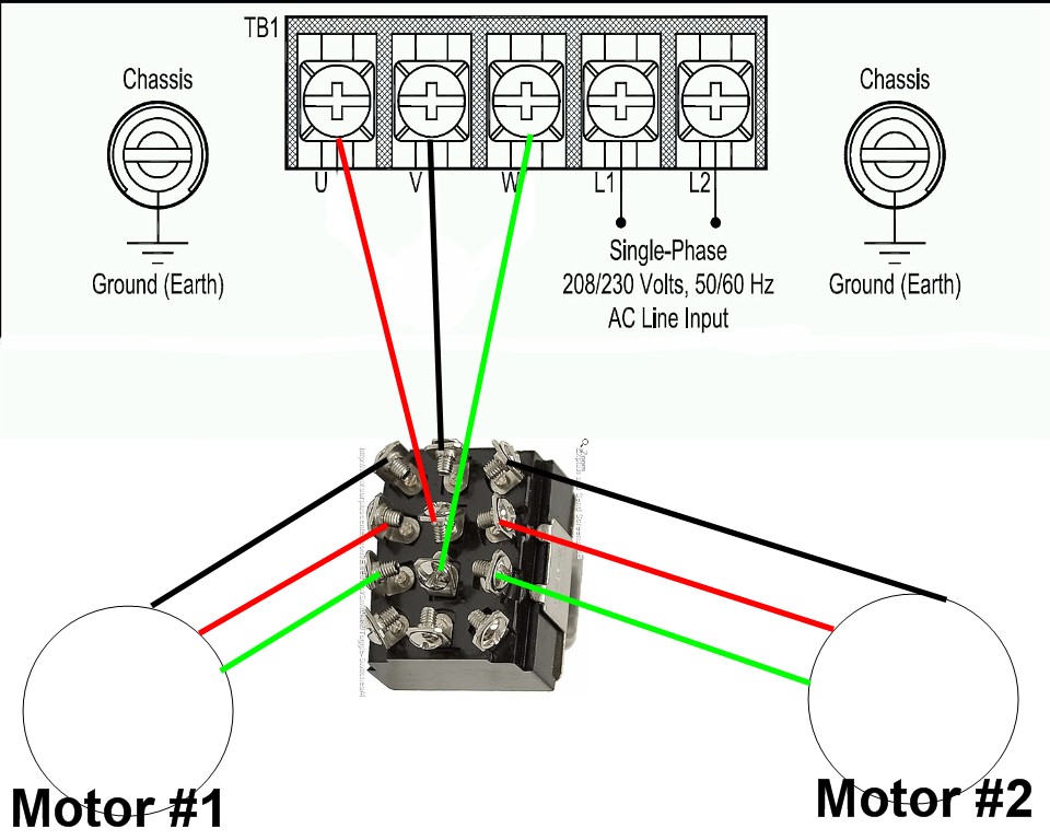
FileVFD wiring diagram.jpg PROBOTIX wiki

Vfd Panel Wiring Diagram Switch Wiring Diagram
How to Control VFD with PLC using Ladder Logic InstrumentationTools
wiring diagram for vfd Wiring Diagram and Schematic